Bringing it all together
Before building the control logic, we want to connect all of the modules to a shared bus and test things out. The modularity of the design makes it easier to test each module by itself so we won't ever get to a point where we put it all together and nothing works.
Videos
Notes
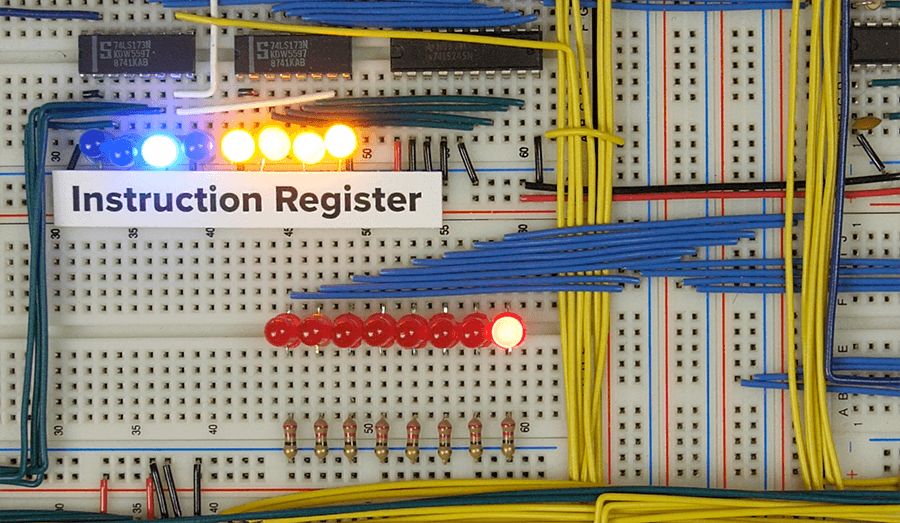
Rather than soldering the LEDs for the bus together as shown in the videos, you can put them in an open space on the breadboard. There will be ample free space on the right side of the breadboard just below the instruction register. Here's what that looks like:
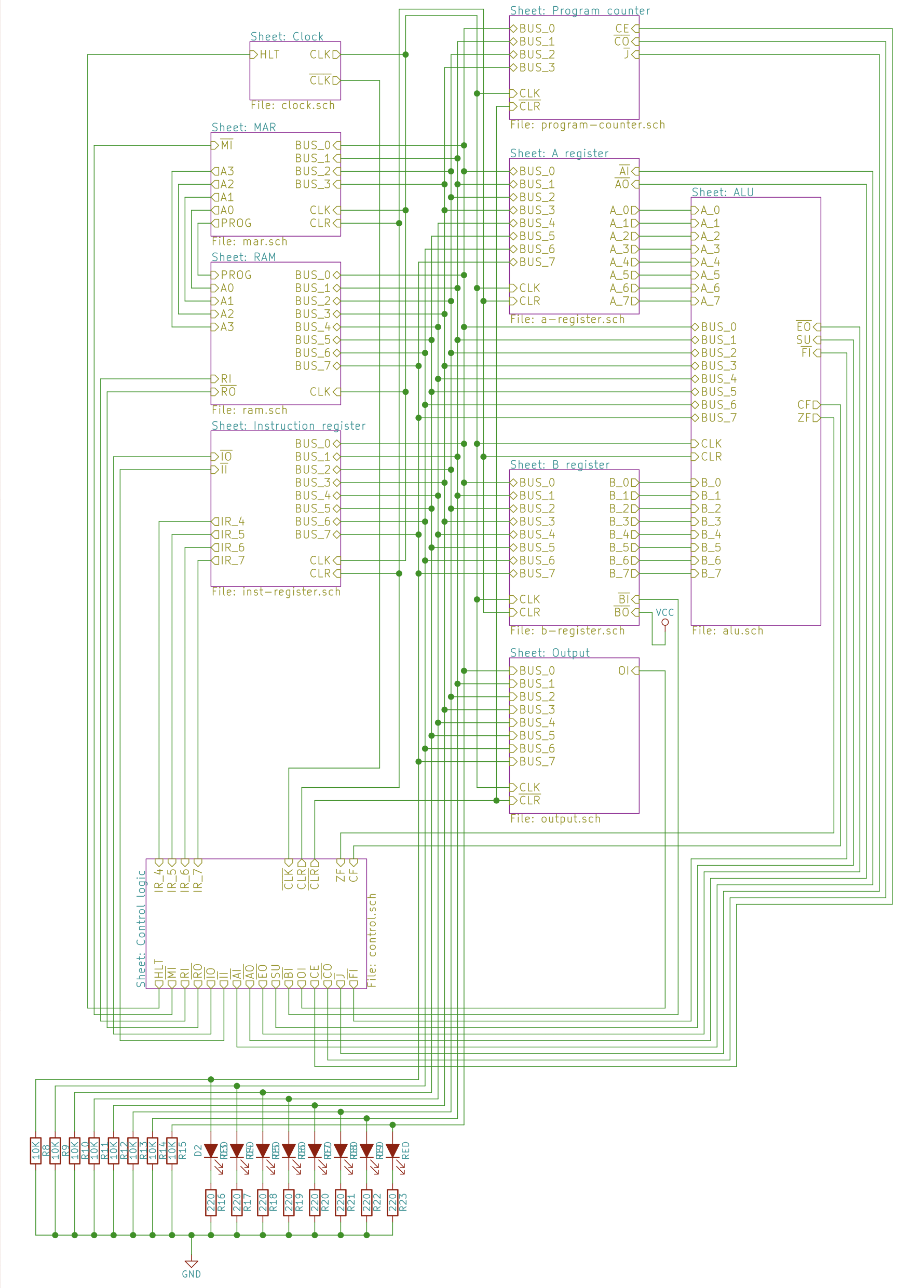
Schematic